Using Newton’s Laws
When analyzing forces and motion, it is important to keep in mind that the world is dominated by resistance. Newton’s ideal, resistance-free world is not easy to visualize. If you analyze a situation and find that the result is different from a similar experience that you have had, ask yourself if this is because of the presence of resistance. In addition, many terms used in physics have everyday meanings that are different from those understood in physics. When talking or writing about physics issues, be careful to use these terms in their precise, scientific way.
Here we will list some of the common types of forces. You will be dealing with many of these throughout your study of physics.
Newton’s Second Law for Circular Motion
Newton's second law indicates that whenever an object accelerates, there must be a net force to create the acceleration. Thus, in uniform circular motion there must be a net force to produce the centripetal acceleration. The second law gives this net force as the product of the object's mass $m$ and its acceleration $v^2/r$. The net force causing the centripetal acceleration is called the centripetal force $\vec{F_c}$ and points in the same direction as the acceleration-that is, toward the center of the circle.
So, the centripetal force is the name given to the net force required to keep an object of mass $m$, moving at a speed $v$, on a circular path of radius $r$, and it has a magnitude of:
$$ F_c=\dfrac{m v^2}{r}$$
The centripetal force always points toward the center of the circle and continually changes direction as the object moves.
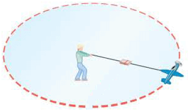 The phrase "centripetal force" does not denote a new and separate force created by nature. The phrase merely labels the net force pointing toward the center of the circular path, and this net force is the vector sum of all the force components that point along the radial direction. Sometimes the centripetal force consists of a single force such as tension, friction, the normal force or a component thereof, or the gravitational force. However, there are circumstances when a number of different forces contribute simultaneously to the centripetal force. In some cases, it is easy to identify the source of the centripetal force, as when a model airplane on a guideline flies in a horizontal circle. The only force pulling the plane inward is the tension in the line, so this force alone ( or a component of it) is the centripetal force.
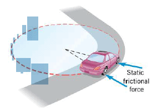 When a car moves at a steady speed around an unbanked curve, the centripetal force keeping the car on the curve comes from the static friction between the road and the tires, as the Figure indicates. It is static, rather than kinetic friction, because the tires are not slipping with respect to the radial direction. If the static frictional force is insufficient, given the speed and the radius of the turn, the car will skid off the road. So an icy road can limit safe driving.
A passenger in this Figure must also experience a centripetal force to remain on the circular path. However, if the upholstery is very slippery, there may not be enough static friction to keep him in place as the car makes a tight turn at high speed. Then, when viewed from inside the car, he appears to be thrown toward the outside of the curve. What really happens is that the passenger slides off on a tangent to the circle, until he encounters a source of centripetal force to keep him in place while the car turns. This occurs when the passenger bumps into the side of the car, which pushes on him with the necessary force.
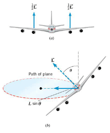 Sometimes the source of the centripetal force is not obvious. A pilot making a turn, for instance, banks or tilts the plane at an angle to create the centripetal force. As a plane flies, the air pushes upward on the wing surfaces with a net lifting force $\vec{L}$ that is perpendicular to the wing surfaces, as the first part of the Figure shows. The second part of the drawing illustrates that when the plane is banked at an angle $\theta$, a component $L \sin \theta$ of the lifting force is directed toward the center of the turn. It is this component that provides the centripetal force. Greater speeds and/or tighter turns require greater centripetal forces. In such situations, the pilot must bank the plane at a larger angle, so that a larger component of the lift points toward the center of the turn. The technique of banking into a turn also has an application in the construction of high-speed roadways, where the road itself is banked to achieve a similar effect.
Banked Curves
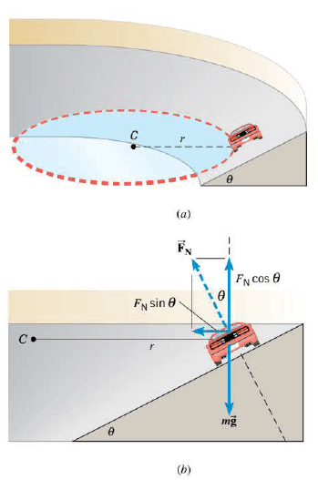 When a car travels without skidding around an unbanked curve, the static frictional force between the tires and the road provides the centripetal force. The reliance on friction can be eliminated completely for a given speed, however, if the curve is banked at an angle relative to the horizontal, much in the same way that a plane is banked while making a turn. The Figure shows a car going around a friction-free banked curve. The radius of the curve is r, where r is measured parallel to the horizontal and not to the slanted surface. Part b shows the normal force $\vec{F_N}$ that the road applies to the car, the normal force being perpendicular to the road. Because the roadbed makes an angle $\theta$ with respect to the horizontal, the normal force has a component $F_N \sin \theta$ that points toward the center C of the circle and provides the centripetal force:
$$ F_c=F_N \sin \theta=\dfrac{m v^2}{r}$$
The vertical component of the normal force is $F_N \cos \theta$ and, since the car does not accelerate in the vertical direction, this component must balance the weight $mg$ of the car. Therefore, $F_N \cos \theta = mg$. Dividing this equation into the previous one shows that:
$$\dfrac{F_N \sin \theta}{F_N \cos \theta} = \dfrac{m v^2/r}{mg}$$ $$\tan \theta = \dfrac{v^2}{r g}$$
This Equation indicates that, for a given speed v , the centripetal force needed for a turn of radius r can be obtained from the normal force by banking the turn at an angle $\theta$, independent of the mass of the vehicle. Greater speeds and smaller radii require more steeply banked curvesthat is, larger values of $\theta$. At a speed that is too small for a given $\theta$, a car would slide down a frictionless banked curve; at a speed that is too large, a car would slide off the top.
Satellites in Circular Orbits using the Law of Universal Gravitation
Today there are many satellites in orbit about the earth. The ones in circular orbits are examples of uniform circular motion. Like a model airplane on a guideline, each satellite is kept on its circular path by a centripetal force. The gravitational pull of the earth provides the centripetal force and acts like an invisible guideline for the satellite.
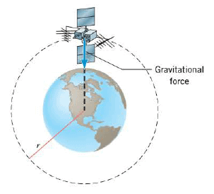 There is only one speed that a satellite can have if the satellite is to remain in an orbit with a fixed radius. To see how this fundamental characteristic arises, consider the gravitational force acting on the satellite of mass m in the Figure. Since the gravitational force is the only force acting on the satellite in the radial direction, it alone provides the centripetal force. Therefore, using Newton's law of gravitation, we have:
$$ F_c= G \dfrac{m M_E}{r^2}=\dfrac{m v^2}{r}$$
where $G$ is the universal gravitational constant, $M_E$ is the mass of the earth, and $r$ is the distance from the center of the earth to the satellite. Solving for the speed $v$ of the satellite gives:
$$v= \sqrt{ \dfrac{G M_E}{r}}$$
If the satellite is to remain in an orbit of radius r, the speed must have precisely this value. Note that the radius r of the orbit is in the denominator in the above Equation. This means that the closer the satellite is to the earth, the smaller is the value for r and the greater the orbital speed must be.
The mass m of the satellite does not appear in the above Equation, having been eliminated algebraically. Consequently, for a given orbit, a satellite with a large mass has exactly the same orbital speed as a satellite with a small mass. However, more effort is certainly required to lift the larger mass satellite into orbit.
The period $T$ of a satellite is the time required for one orbital revolution. As in any uniform circular motion, the period is related to the speed of the motion by $v = 2 \pi r/ T$. Substituting v from the orbital speed Equation shows that:
$$\dfrac{2 \pi r}{T}= \sqrt{ \dfrac{G M_E}{r}}$$
Solving this expression for the period T gives:
$$T= \dfrac{2 \pi r^{\frac{3}{2}}}{\sqrt{ G M_E}}$$
Although derived for earth orbits, this Equation can also be used for calculating the periods of those planets in nearly circular orbits about the sun, if $M_E$ is replaced by the mass $M_s$ of the sun and r is interpreted as the distance between the center of the planet and the center of the sun. The fact that the period is proportional to the three-halves power of the orbital radius is known as Kepler's third law, and it is one of the laws discovered by Johannes Kepler (1571-1630) during his studies of planetary motion. Kepler's third law also holds for elliptical orbits.
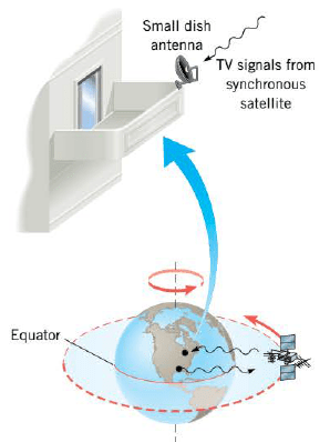 An important application of period Equation occurs in the field of communications, where "synchronous satellites" are put into a circular orbit that is in the plane of the equator, as the Figure shows. The orbital period is chosen to be one day, which is also the time it takes for the earth to turn once about its axis. Therefore, these satellites move around their orbits in a way that is synchronized with the rotation of the earth. For earth-based observers, synchronous satellites have the useful characteristic of appearing in fixed positions in the sky and can serve as "stationary" relay stations for communication signals sent up from the earth's surface.
The idea of life on board an orbiting satellite conjures up visions of astronauts floating around in a state of "weightlessness". Actually, this state should be called "apparent weightlessness," because it is similar to the condition of zero apparent weight that occurs in an elevator during free-fall.
Digital lab: Newton’s Cannon
|
Digital Figure: Road Conditions and Safe Driving
|
Digital Interactives: Circular Motion
|
|---|---|---|
Digital Figure: Banked Curves
|
Digital Figure: loop-the-loop motorcycle
|
Animated Physics: Centripetal Force
|
Interactive Demonstration: Centripetal Force
|
Solution Tutor: Period and Speed of an Orbiting Object
|
Digital Interactives: Banked Curve
|
Newton’s Second Law for Rotational Motion
We have seen many examples of how a net force affects linear motion by causing an object to accelerate. We now need to take into account the possibility that a rigid object can also have an angular acceleration. A net external force causes linear motion to change, but what causes rotational motion to change? For example, something causes the rotational velocity of a speedboat's propeller to change when the boat accelerates. Is it simply the net force? As it turns out, it is not the net external force, but rather the net external torque that causes the rotational velocity to change. Just as greater net forces cause greater linear accelerations, greater net torques cause greater rotational or angular accelerations.
Torques on Rigid Objects
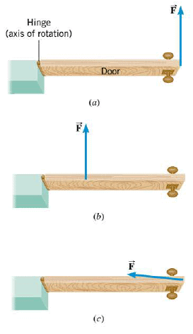 To make an object start rotating about an axis clearly requires a force. But the direction of this force, and where it is applied, are also important. The Figure helps to explain the idea of torque. When you push on a door with a force $\vec{F}$, as in part a, the door opens more quickly when the force is larger. Other things being equal, a larger force generates a larger torque. However, the door does not open as quickly if you apply the same force at a point closer to the hinge, as in part b, because the force now produces less torque. Furthermore, if your push is directed nearly at the hinge, as in part c, you will have a hard time opening the door at all, because the torque is nearly zero. In summary, the torque depends on the magnitude of the force, on the point where the force is applied relative to the axis of rotation (the hinge in the Figure), and on the direction of the force.
For simplicity, in the figure part a and part b we deal with situations in which the force lies in a plane that is perpendicular to the axis of rotation, and only this one force acts, the angular acceleration of the door is proportional not only to the magnitude of the force, but is also directly proportional to the distance between the line of action (an extended line drawn colinear with the force) and the axis of rotation, measured on a line that is perpendicular to both. This distance is called the lever arm ($l$), or moment arm, of the force.
The angular acceleration, then, is proportional to the product of the force times the lever arm. This product is called the moment of the force about the axis, or, more commonly, it is called the torque, and is represented by $\tau$ (Greek lowercase letter tau). So: $\alpha \propto \tau$, This is the rotational analog of Newton’s second law for linear motion, $a \propto F$.
Magnitude of torque: $\tau = F l$
Direction of torque: The torque $\tau$ is positive when the force tends to produce a counterclockwise rotation about the axis, and negative when the force tends to produce a clockwise rotation.
SI Unit of Torque: newton.meter (N.m)
The lever arm for a force such as $\vec{F}$ is found by drawing a line along the direction of $\vec{F}$ (this is the “line of action” of $\vec{F}$). Then we draw another line, perpendicular to this line of action, that goes to the axis of rotation and is perpendicular also to it. The length of this second line is the lever arm for $\vec{F}$ :
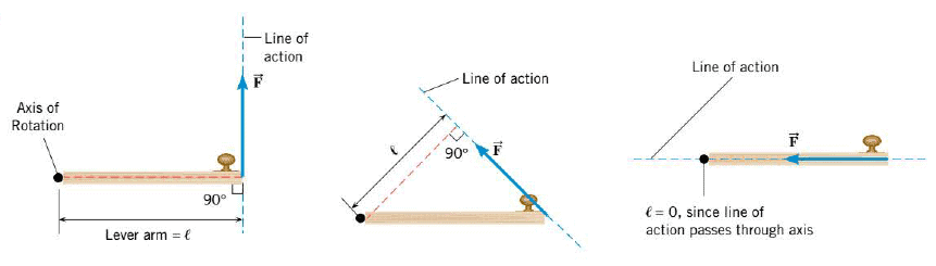
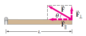 An equivalent way of determining the torque associated with a force is to resolve the force into components parallel and perpendicular to the line that connects the axis to the point of application of the force, as shown in the Figure. The component $F_{\parallel }$ exerts no torque since it is directed at the rotation axis (its lever arm is zero). Hence the torque will be equal to $F_{\perp }$ times the distance $l$ from the axis to the point of application of the force:
$$\tau = l F = l F \sin \theta $$
Center of Gravity
Often, it is important to know the torque produced by the weight of an extended body and the arm. In all cases the weight is considered to act at a definite point for the purpose of calculating the torque. This point is called the center of gravity (abbreviated "cg").
The center of gravity of a rigid body is the point at which its weight can be considered to act when the torque due to the weight is being calculated.
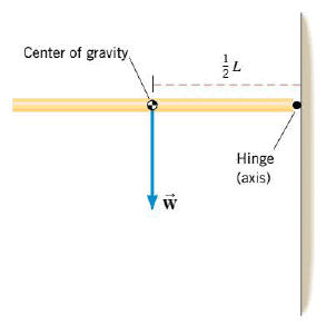 When an object has a symmetrical shape and its weight is distributed uniformly, the center of gravity lies at its geometrical center. For instance, the Figure shows a thin, uniform, horizontal rod of length $L$ attached to a vertical wall by a hinge. The center of gravity of the rod is located at the geometrical center. The lever arm for the weight W is $L/2$, and the magnitude of the torque is $W(L/2)$. In a similar fashion, the center of gravity of any symmetrically shaped and uniform object, such as a sphere, disk, cube, or cylinder, is located at its geometrical center. However, this does not mean that the center of gravity must lie within the object itself. The center of gravity of a compact disc recording, for instance, lies at the center of the hole in the disc and is, therefore, "outside" the object.
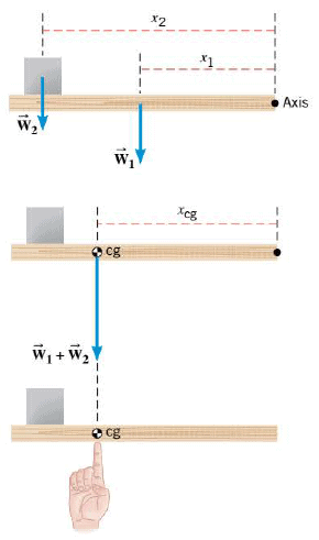 Suppose we have a group of objects, with known weights and centers of gravity, and it is necessary to know the center of gravity for the group as a whole. As an example, the Figure shows a group composed of two parts: a horizontal uniform board (weight $\vec{W_1}$ ) and a uniform box (weight $\vec{W_2}$ ) near the left end of the board. The center of gravity can be determined by calculating the net torque created by the board and box about an axis that is picked arbitrarily to be at the right end of the board. First part a of the figure shows the weights $\vec{W_1}$ and $\vec{W_2}$ and their corresponding lever arums $x_1$ and $x_2$. The net torque is $\sum \tau=W_1 x_1 + W_2 x_2$ . It is also possible to calculate the net torque by treating the total weight $\vec{W_1} + \vec{W_2}$ as if it were located at the center of gravity and had the lever arm $x_{cg}$ as the second part of the drawing indicates: $\sum \tau = (W_1 + W_2 ) x_{cg}$ . The two values for the net torque must be the same, so that:
$$W_1 x_1 + W_2 x_2=(W_1 + W_2 ) x_{cg}$$
This expression can be solved for $x_{cg}$, which locates the center of gravity relative to the axis:
$$x_{cg}= \dfrac{W_1 x_1 + W_2 x_2 +...}{W_1 + W_2 +...}$$
The notation "+... " indicates that this Equation can be extended to account for any number of weights distributed along a horizontal line. The Figure illustrates that the group can be balanced by a single external force (due to the index finger), if the line of action of the force passes through the center of gravity, and if the force is equal in magnitude, but opposite in direction, to the weight of the group.
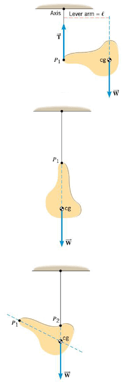 The center of gravity of an object with an irregular shape and a nonuniform weight distribution can be found by suspending the object from two different points $P_1$ and $P_2$, one at a time. The first part of the Figure shows the object at the moment of release, when its weight $\vec{W}$, acting at the center of gravity, has a nonzero lever arm $l$ relative to the axis shown in the drawing. At this instant the weight produces a torque about the axis. The tension force $\vec{T}$ applied to the object by the suspension cord produces no torque because its line of action passes through the axis. Hence, in the first part there is a net torque applied to the object, and the object begins to rotate. Friction eventually brings the object to rest as in the second part, where the center of gravity lies directly below the point of suspension. In such an orientation, the line of action of the weight passes through the axis, so there is no longer any net torque. In the absence of a net torque the object remains at rest. By suspending the object from a second point $P_2$ (see the third part of the Figure), a second line through the object can be established, along which the center of gravity must also lie. The center of gravity, then, must be at the intersection of the two lines.
Moment of Inertia
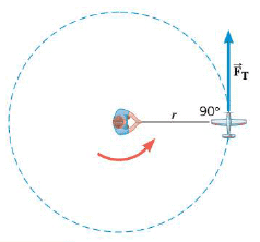 The goal of this section is to put Newton's second law into a form suitable for describing the rotational motion of a rigid object about a fixed axis. We begin by considering a particle moving on a circular path. The Figure presents a good approximation of this situation by using a small model plane on a guideline of negligible mass. The plane's engine produces a net external tangential force $F_T$ that gives the plane a tangential acceleration $a_T$. In accord with Newton's second law, it follows that $F_T = m a_T$. The torquer produced by this force is $\tau = F_T r$, where the radius r of the circular path is also the lever arm. As a result, the torque is $\tau = m a_T r$. However, the tangential acceleration is related to the angular acceleration a according to $a_T = r \alpha$, where a must be expressed in rad/s$^2$, then the torque becomes:
$$\tau = (mr^2) \alpha$$
This Equation is the form of Newton's second law we have been seeking. It indicates that the net external torque $\tau$ is directly proportional to the angular acceleration $\alpha$. The constant of proportionality is $I= mr^2$, which is called the moment of inertia of the particle. The SI unit for moment of inertia is kg.m$^2$ .
The advantage in using $\tau = (mr^2) \alpha$ is that it can be applied to any rigid body rotating about a fixed axis, and not just to a particle. The rigid body is composed of a number of mass particles, $m_1$, $m_2$, ... , $m_N$, where N is very large. Each particle behaves in the same way as the model airplane in the Figure and obeys the Equation $\tau = (mr^2) \alpha$ . Each particle has the same angular acceleration $\alpha$, since the rotating object is assumed to be rigid. Adding together the N equations and factoring out the common value of $\alpha$, we find that:
$$\sum \tau = (\sum mr^2) \alpha$$
where the expression $\sum \tau$ is the sum of the external torques, and $\sum mr^2$ represents the sum of the individual moments of inertia. The latter quantity is the moment of inertia $I$ of the body:
$$I = m_1 r_1^2 + m_2 r_2^2 + ... + m_N r_N^2 = \sum mr^2 $$
In this equation, r is the perpendicular radial distance of each particle from the axis of rotation. All this equations gives the following result ($\alpha$ must be expressed in rad/s$^2$):
$$\sum \tau = I \alpha$$
The version of Newton's second law applies only for rigid bodies. The word "rigid" means that the distances $r_1$, $r_2$, $r_3$ , etc. that locate each particle $m_1$, $m_2$, $m_3$, etc. do not change during the rotational motion. In other words, a rigid body is one that does not change its shape while undergoing an angular acceleration in response to an applied net external torque.
The form of the second law for rotational motion is similar to the equation for translational (linear) motion and is valid only in an inertial frame. The moment of inertia $I$ plays the same role for rotational motion that the mass $m$ does for translational motion. Thus, $I$ is a measure of the rotational inertia of a body.
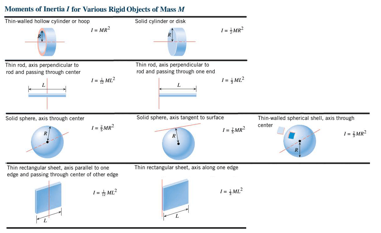
It can be seen that the moment of inertia depends on both the mass of each particle and its distance from the axis of rotation. The farther a particle is from the axis, the greater is its contribution to the moment of inertia. Therefore, although a rigid object possesses a unique total mass, it does not have a unique moment of inertia. The moment of inertia can change when the axis of rotation changes. We can use integral calculus to evaluate the moment of inertia of a rigid object with a continuous mass distribution, and the following Table gives some typical results. These results depend on the total mass of the object, its shape, and the location and orientation of the axis.
Digital simulation: Net Torque and Angular Motion
|
Digital simulation: Newton's Second Law of Rotation
|
|
|---|---|---|
Digital Figure: Torque
|
Digital Figure: Moment of Inertia
|
Animated Physics: Torque
|
Interactive Demonstration: Torque
|
Digital figure: Center of Gravity of a Cargo Plane
|
Drag Force and Terminal Velocity
It is true that the particles in the air around an object exert forces on it. Air actually exerts a huge force, but in most cases, it exerts a balanced force on all sides, and therefore it has no net effect. Can you think of any experiences that help to prove that air exerts a force? When you stick a suction cup on a smooth wall or table, you remove air from the “inside” of it. The suction cup is difficult to remove because of the net force of the air on the “outside.”
So far, you have neglected the force of air on an object moving through the air. In actuality, when an object moves through any fluid, such as air or water, the fluid exerts a drag force on the moving object in the direction opposite to its motion. A drag force is the force exerted by a fluid on the object moving through the fluid. This force is dependent on the motion of the object, the properties of the object, and the properties of the fluid that the object is moving through. For example, as the speed of the object increases, so does the magnitude of the drag force. The size and shape of the object also affects the drag force. The drag force is also affected by the properties of the fluid, such as its viscosity and temperature.
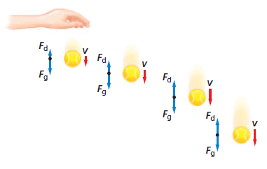 If you drop a table-tennis ball, as in the Figure, it has very little velocity at the start, and thus only a small drag force. The downward force of gravity is much stronger than the upward drag force, so there is a downward acceleration. As the ball’s velocity increases, so does the drag force. Soon, the drag force equals the force of gravity. When this happens, there is no net force, and so there is no acceleration. The constant velocity that is reached when the drag force equals the force of gravity is called the terminal velocity.
When light objects with large surface areas are falling, the drag force has a substantial effect on their motion, and they quickly reach terminal velocity. Heavier, more-compact objects are not affected as much by the drag force. For example, the terminal velocity of a table-tennis ball in air is 9 m/s, that of a basketball is 20 m/s, and that of a baseball is 42 m/s. Competitive skiers increase their terminal velocities by decreasing the drag force on them. They hold their bodies in an egg shape and wear smooth clothing and streamlined helmets. Sky divers can increase or decrease their terminal velocity by changing their body orientation and shape. A horizontal, spread-eagle shape produces the slowest terminal velocity, about 60 m/s. Because a parachute changes the shape of the sky diver when it opens, a sky diver becomes part of a very large object with a correspondingly large drag force and a terminal velocity of about 5 m/s.
Equilibrium Applications of Newton's Laws of Motion
According to Newton’s first law, a net force is something that causes the velocity of an object to change. If the net force on an object is zero, then the object is in equilibrium. In physics, the word "equilibrium" also refers to a lack of change, but in the sense that the velocity of an object isn't changing. If its velocity doesn't change, an object is not accelerating. Our definition of equilibrium, then, is as follows:
An object is in equilibrium when it has zero acceleration.
Since the acceleration is zero for an object in equilibrium, all of the acceleration components are also zero. In two dimensions, this means that $a_x = 0$ m/s$^2$ and $a_y = 0$ m/s$^2$ . Substituting these values into the second law ($\sum F_x = m a_x$ and $\sum F_y = m a_y$) shows that the x component and the y component of the net force must each be zero. In other words, the forces acting on an object in equilibrium must balance. Thus, in two dimensions, the equilibrium condition is expressed by two equations:
$$\sum F_x = 0$$ $$\sum F_y = 0$$
Use the above two Equations to solve equilibrium problems. Note that an object can be moving and still be in equilibrium, provided there is no acceleration.
When forces act on a rigid object, they can affect its motion in two ways. They can produce a translational acceleration a (components $a_x$ and $a_y$)· The forces can also produce torques, which can cause the object to have an angular acceleration $\alpha$. In general, we can deal with the resulting combined motion by using Newton's second law. For the translational motion, we use the law in the form $\sum F = m a$ . For the rotational motion of a rigid object about a fixed axis, we use the law in the form $\sum \tau = I \alpha$. When $a$ (both components) and $\alpha$ are zero, there is no acceleration of any kind, and the object is in equilibrium. If any component of a is nonzero or if $\alpha$ is nonzero, we have accelerated motion, and the object is not in equilibrium.
Digital simulation: Rotational Equilibrium
|
Digital Interactives: Ladder
|
|---|
Motion Along an Inclined Plane
You have applied Newton’s laws to a variety of equilibrium situations, to motions that were either horizontal or vertical. How would you apply them in a situation like in which a skier glides down a slope?
Start by identifying the forces acting on the object, the skier, as shown in the second part of the Figure and sketching a free-body diagram. The gravitational force on the skier is in the downward direction toward the center of Earth. There is a normal force perpendicular to the hill, and the frictional forces opposing the skier’s motion are parallel to the hill. The resulting free-body diagram is shown in the third part of the Figure. You can see that, other than the force of friction, only one force acts horizontally or vertically, and you know from experience that the acceleration of the skier will be along the slope. How do you find the net force that causes the skier to accelerate?
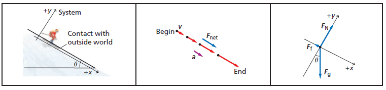
The most important decision in problems involving motion along a slope is what coordinate system to use. Because an object’s acceleration is usually parallel to the slope, one axis, usually the x-axis, should be in that direction. The y-axis is perpendicular to the x-axis and perpendicular to the surface of the slope. With this coordinate system, you now have two forces, the normal and frictional forces, in the directions of the coordinate axes; however, the weight is not. This means that when an object is placed on an inclined plane, the magnitude of the normal force between the object and the plane will usually not be equal to the object’s weight.
You will need to apply Newton’s laws once in the x-direction and once in the y-direction. Because the weight does not point in either of these directions, you will need to break this vector into its x- and y-components before you can sum your forces in these two directions.
Digital lab: Inclined Plane
|
Digital simulation: Static Friction
|
Interactive Demonstration: Net Force
|
|---|---|---|
Digital Interactives: Inclined Plane
|

You don`t have permission to comment here!
Report