Electric Circuits and Kirchhoff's Rules

Electric circuits are the basis of every electric device, from electric lights to microwave ovens to computers. Learning how circuits work will help you understand how countless electric devices function.
A mountain river can be used to model an electric circuit. From its source high in the mountains, the river flows downhill to the plains below. No matter which path the river takes, its change in elevation, from the mountaintop to the plain, is the same. Some rivers flow downhill in a single stream. Other rivers may split into two or more smaller streams as they flow over a waterfall or through a series of rapids. In this case, part of the river follows one path, while other parts of the river follow different paths. No matter how many paths the river takes, however, the total amount of water flowing down the mountain remains unchanged. In other words, the amount of water flowing downhill is not affected by the path it takes.
How does the river model an electric circuit? The distance that the river drops is similar to the potential difference in a circuit. The amount of water flowing in the river is similar to current in a circuit. Narrow rapids create resistance and are similar to resistors in a circuit. What part of a river is similar to a battery or a generator in an electric circuit? The energy source needed to raise water to the top of the mountain is the Sun. Solar energy evaporates water from lakes and seas leading to the formation of clouds that release rain or snow that falls on the mountaintops. Continue to think about the mountain river model as you read about the current in electric circuits.
Digital lesson: What Are Electric Circuits?
|
Digital lab: What Is An Electric Circuits?
|
Digital lesson: Electric Circuits?
|
|---|
Resistors in Series and Parallel
Three students are connecting two identical lamps to a battery. Before they make the final connection to the battery, their teacher asks them to predict the brightnesses of the two lamps. Each student knows that the brightness of a lamp depends on the current through it. The first student predicts that only the lamp close to the positive (+) terminal of the battery will light because all the current will be used up as thermal and light energy. The second student predicts that only part of the current will be used up, and the second lamp will glow, but more brightly than the first. The third student predicts that the lamps will be of equal brightness because current is a flow of charge and the charge leaving the first lamp has nowhere else to go in the circuit except through the second lamp. The third student reasons that because the current will be the same in each lamp, the brightness also will be the same. How do you predict the lights will behave? If you consider the mountain river model for this circuit, you will realize that the third student is correct.
Series Wiring
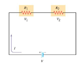 Series wiring means that the devices are connected in such a way that there is the same electric current through each device. The Figure shows a circuit in which two different devices, represented by resistors $R_1$ and $R_2$, are connected in series with a battery. Note that if the current in one resistor is interrupted, the current in the other is too. This could occur, for example, if two light bulbs were connected in series and the filament of one bulb broke. Because of the series wiring, the voltage $V$ supplied by the battery is divided between the two resistors. The drawing indicates that the portion of the voltage across $R_1$ is $V_1$, while the portion across $R_2$ is $V_2$, so $V = V_1 + V_2$. For the individual resistances, the definition of resistance indicates that $R_1 = \dfrac{V_1}{I}$ and $R_2 = \dfrac{V_2}{I}$ , so that $V_1 = IR_1$ and $V_2 = IR_2$. Therefore, we have:
$$V = V_1 + V_2 = IR_1 + IR_2 = I (R_1 + R_2) = IR_s$$
where $R_s$ is called the equivalent resistance of the series circuit. Thus, two resistors in series are equivalent to a single resistor whose resistance is $R_s = R_1 + R_2$, in the sense that there is the same current through $R_s$ as there is through the series combination of $R_1$ and $R_2$ . This line of reasoning can be extended to any numlber of resistors in series if we note the following:
The voltage across all the resistors in series is the sum of the individual voltages across each resistor.
The total power delivered to any number of resistors in series is equal to the power delivered to the equivalent resistance.
$$P=\dfrac{V^2}{R_s}$$
Parallel Wiring
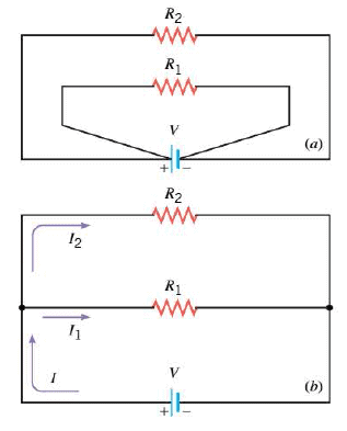 Parallel wiring is another method of connecting electrical devices .. Parallel wiring means that the devices are connected in such a way that the same voltage is applied across each device. The Figure shows two resistors connected in parallel between the terminals of a battery. Part a of the picture is drawn so as to emphasize that the entire voltage of the battery is applied across each resistor. Actually, parallel connections are rarely drawn in this manner; instead they are drawn as in part b, where the dots indicate the points where the wires for the two branches are joined together. Figures a and b are equivalent representations of the same circuit.
When two resistors $R_1$ and $R_2$ are connected as in the Figure, each receives current from the battery as if the other were not present. Therefore, $R_1$ and $R_2$ together draw more current from the battery than does either resistor alone.
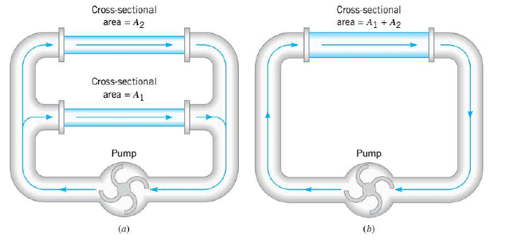 According to the definition of resistance, $R = V/I$, a larger current implies a smaller resistance. Thus, the two parallel resistors behave as a single equivalent resistance that is smaller than either $R_1$ or $R_2$. The Figure returns to the water-flow analogy to provide additional insight into this important feature of parallel wiring. In part a, two sections of pipe that have the same length are connected in parallel with a pump. In part b these two sections have been replaced with a single pipe of the same length, whose cross-sectional area equals the combined cross-sectional areas of section 1 and section 2. The pump (analogous to a voltage source) can push more water per second (analogous to current) through the wider pipe in part b (analogous to a wider wire) than it can through either of the narrower pipes (analogous to narrower wires) in part a. In effect, the wider pipe offers less resistance to the flow of water than either of the narrower pipes offers individually. As in a series circuit, it is possible to replace a parallel combination of resistors with an equivalent resistor that results in the same total current and power for a given voltage as the original combination. To determine the equivalent resistance for the two resistors in parallel, note that the total current $I$ from the battery is the sum of $I_1$ and $I_2$, where $I_1$ is the current in resistor $R_1$ and $I_2$ is the current in resistor $R_2$:
$$I= I_1 + I_2$$
Since the same voltage $V$ is applied across each resistor, the definition of resistance indicates that $I_1= \dfrac{V}{R_1}$, and $I_2= \dfrac{V}{R_2}$. Therefore:
$$I = I_1 + I_2 = \dfrac{V}{R_1} + \dfrac{V}{R_2} = V \left(\dfrac{1}{R_1} + \dfrac{1}{R_2} \right) = V \left( \dfrac{1}{R_p} \right)$$
where $R_p$ is the equivalent resistance. Hence, when two resistors are connected in parallel, they are equivalent to a single resistor whose resistance $R_p$ can be obtained from $\dfrac{1}{R_p} = \dfrac{1}{R_1} + \dfrac{1}{R_2}$.
For any number of resistors wired in parallel, the total current from the voltage source is the sum of the currents in the individual resistors. Thus, a similar line of reasoning reveals that the equivalent resistance is:
$$\dfrac{1}{R_p} = \dfrac{1}{R_1} + \dfrac{1}{R_2} + \dfrac{1}{R_3}+ ...$$
In a parallel combination of resistances, it is the smallest resistance that has the largest impact in determining the equivalent resistance. In fact, if one resistance approaches zero, then according to the above Equation, the equivalent resistance also approaches zero. In such a case, the near-zero resistance is said to short out the other resistances by providing a near-zero resistance path for the current to follow as a shortcut around the other resistances.
The total power delivered to any number of resistors in parallel is equal to the power delivered to the equivalent resistor:
$$P= I^2 R_p$$
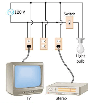 Parallel wiring is very common. For example, when an electrical appliance is plugged into a wall socket, the appliance is connected in parallel with other appliances, as in the Figure, where the entire voltage of 120 V is applied across each one of the devices: the television, the stereo, and the light bulb (when the switch is turned on). The presence of the unused socket or other devices that are turned off does not affect the operation of those devices that are turned on. Moreover, if the current in one device is interrupted (perhaps by an opened switch or a broken wire), the current in the other devices is not interrupted. In contrast, if household appliances were connected in series, there would be no current through any appliance if the current in the circuit were halted at any point.
Circuits Wired Partially in Series and Partially in Parallel
Often an electric circuit is wired partially in series and partially in parallel. The key to determining the current, voltage, and power in such a case is to deal with the circuit in parts, with the resistances in each part being either in series or in parallel with each other.
Internal Resistance
So far, the circuits we have considered include batteries or generators that contribute only their emfs to a circuit. In reality, however, such devices also add some resistance. This resistance is called the internal resistance of the battery or generator because it is located inside the device. In a battery, the internal resistance is due to the chemicals within the battery. In a generator, the internal resistance is the resistance of wires and other components within the generator.
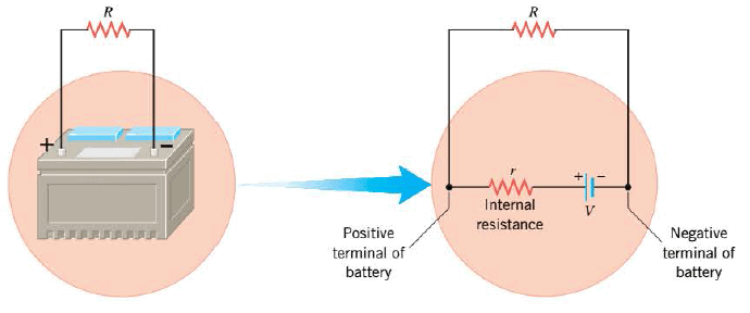 The Figure presents a schematic representation of the internal resistance $r$ of a battery. The drawing emphasizes that when an external resistance $R$ is connected to the battery, the resistance is connected in series with the internal resistance. The internal resistance of a functioning battery is typically small (several thousandths of an ohm for a new car battery). Nevertheless, the effect of the internal resistance may not be negligible. When current is drawn from a battery, the internal resistance causes the voltage between the terminals to drop below the maximum value specified by the battery's emf. The actual voltage between the terminals of a battery is known as the terminal voltage.
The terminal voltage of a battery is smaller when the current drawn from the battery is larger, an effect that any car owner can demonstrate. Turn the headlights on before starting your car, so that the current through the battery is about 10 A, then start the car. The starter motor draws a large amount of additional current from the battery, momentarily increasing the total current by an appreciable amount. Consequently, the terminal voltage of the battery decreases, causing the headlights to become dimmer.
Animated Physics: Equivalent Resistance for Resistors in Parallel
|
Animated Physics: Resistors in Circuits
|
Concept Map: Electric Circuits
|
|---|---|---|
Interactive Demonstration: Equivalent Resistance
|
Interactive Demonstration: Current in and Potential Difference Across a Resistor
|
Solution Tutor: Resistors in Parallel
|
Digital Investigation: Electric Circuits
|
Digital simulation: Series and Parallel Circuits
|
Digital simulation: Comparing the Brightness of Light Bulbs
|
Digital Figurw: filaments
|
Kirchhoff’s Rules
Electric circuits that contain a number of resistors can often be analyzed by combining individual groups of resistors in series and parallel, as we discusses above. However, there are many circuits in which no two resistors are in series or in parallel. To deal with such circuits it is necessary to employ methods other than the series-parallel method. One alternative is to take advantage of Kirchhoff's rules, named after their developer Gustav Kirchhoff (1824-1887). There are two rules, the junction rule and the loop rule, and both arise from principles and ideas that we have encountered earlier. The junction rule is an application of the law of conservation of electric charge to the electric current in a circuit. The loop rule is an application of the principle of conservation of energy to the electric potential that exists at various places in a circuit.
Digital simulation: Kirchhoff's Rules
|
Digital Figure: car battery
|
|---|
Measurement of Current and Voltage (DC Voltmeters and Ammeters)
Current and voltage can be measured with devices known, respectively, as ammeters and voltmeters. There are two types of such devices: those that use digital electronics and those that do not. The essential feature of nondigital devices is the de galvanometer. A galvanometer consists of a magnet, a coil of wire, a spring, a pointer, and a calibrated scale. The coil is mounted so that it can rotate, which causes the pointer to move in relation to the scale. The coil rotates in response to the torque applied by the magnet when there is a current in the coil. The coil stops rotating when this torque is balanced by the torque of the spring.
Two characteristics of a galvanometer are important when it is used as part of a measurement device. First, the amount of dc current that causes full-scale deflection of the pointer indicates the sensitivity of the galvanometer. For instance, an instrument that deflects full scale when the current in the coil is 0.10 mA. The second important characteristic is the resistance $R_c$ of the wire in the coil.
Capacitors in Series and in Parallel
All capacitors in parallel, have the same voltage V across their plates. However, the capacitors contain different amounts of charge.
All capacitors in series, regardless of their capacitances, contain charges of the same magnitude, +q and -q, on their plates.
RC Circuits
Many electric circuits contain both resistors and capacitors (a resistor-capacitor circuit), or RC circuit.
Digital simulation: Charging a Capacitor
|
|---|
Safety and the Physiological Effects of Current
Electric circuits, although very useful, can also be hazardous. To reduce the danger inherent in using circuits, proper electrical grounding is necessary.

You don`t have permission to comment here!
Report