Electric Current, Resistance, Power and Ohm’s Law
As you learned before, flowing water at the top of a waterfall has both potential and kinetic energy. However, the large amount of natural potential and kinetic energy available from resources such as Niagara Falls are of little use to people or manufacturers who are 100 km away, unless that energy can be transported efficiently. Electric energy provides the means to transfer large quantities of energy great distances with little loss. This transfer usually is done at high potential differences through power lines, such as those shown in the photo on the right. Once this energy reaches the consumer, it can easily be converted into another form or combination of forms, including sound, light, thermal energy, and motion.
Because electric energy can so easily be changed into other forms, it has become indispensable in our daily lives. Even quick glances around you will likely generate ample examples of the conversion of electric energy. Inside, lights to help you read at night, microwaves and electric ranges to cook food, computers, and stereos all rely on electricity for power. Outside, street lamps, store signs, advertisements, and the starters in cars all use flowing electric charges.
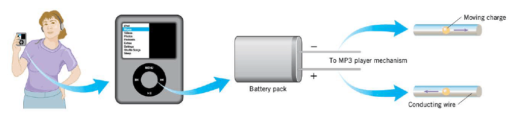
As the Figure illustrates, The transfer of energy takes place via an electric circuit, in which energy is transferred from a source (the battery pack) to a device (the MP3 player) by charges that move through a conducting wire.
Here, you will learn how potential differences, resistance, and current are related. You also will learn about electric power and energy transfer.
Digital lesson: Electric Current?
|
|---|
Electric Current (Rate of Charge Flow)
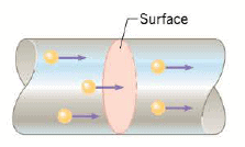 The flow of charge is known as an electric current. The electric current $I$ is defined as the amount of charge per unit time that crosses the imaginary surface (that is perpendicular to their motion), as in Figure, in much the same sense that a river current is the amount of water per unit time that is flowing past a certain point.
If the rate is constant, the current is:
$$I= \dfrac{ \Delta q}{\Delta t}$$
If the rate of flow is not constant, then this Equation gives the average current. Since the units for charge and time are the coulomb (C) and the second (s), the SI unit for current is a coulomb per second (C/s). One coulomb per second is referred to as an ampere (A), after the French mathematician Andre-Marie Ampere (1775- 1836).
If the charges move around a circuit in the same direction at all times, the current is said to be direct current (dc), which is the kind produced by batteries. In contrast, the current is said to be alternating current (ac) when the charges move first one way and then the opposite way, changing direction from moment to moment. Many energy sources produce alternating current-for example, generators at power companies and microphones.
Producing Electric Current
You learned that when two conducting spheres touch, charges flow from the sphere at a higher potential to the one at a lower potential. The flow continues until there is no potential difference between the two spheres. A flow of charged particles is an electric current.
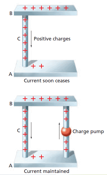 In the first Figure, two conductors, A and B, are connected by a wire conductor, C. Charges flow from the higher potential difference of B to A through C. This flow of positive charge is called conventional current. The flow stops when the potential difference between A, B, and C is zero.
You could maintain the electric potential difference between B and A by pumping charged particles from A back to B, as illustrated in the second Figure. Since the pump increases the electric potential energy of the charges, it requires an external energy source to run. This energy could come from a variety of sources. One familiar source, a voltaic or galvanic cell (a common dry cell), converts chemical energy to electric energy. Several galvanic cells connected together are called a battery. A second source of electric energy—a photovoltaic cell, or solar cell—changes light energy into electric energy.
*Historically, it was believed that positive charges flow in the wires of an electric circuit. Today, it is known that negative charges flow in wires from the negative toward the positive terminal. Here, however, we follow the customary practice of describing the flow of negative charges by specifying the opposite but equivalent flow of positive charges. This hypothetical flow of positive charges is called the "conventional electric current,".
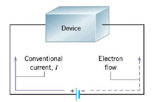 In the Figure, negative electrons leave the negative terminal of the battery, pass through the device, and arrive at the positive terminal. The same effect would have been achieved if an equivalent amount of positive charge had left the positive terminal, passed through the device, and arrived at the negative terminal. Therefore, the drawing shows the conventional current originating from the positive terminal and moving clockwise around the circuit. A conventional current of hypothetical positive charges is consistent with our earlier use of a positive test charge for defining electric fields and potentials. The direction of conventional current is always from a point of higher potential toward a point of lower potential- that is, from the positive toward the negative terminal. Here the symbol $I$ stands for conventional current.
Conservation of charge
Charges cannot be created or destroyed, but they can be separated. Thus, the total amount of charge (the number of negative electrons and positive ions) in the circuit (Any closed loop or conducting path allowing electric charges to flow) does not change. If one coulomb flows through the battery in 1 s, then one coulomb also will flow through the lamp in 1 s. Thus, charge is a conserved quantity.
Energy also is conserved. The change in electric energy, $\Delta E$, equals $qV$. Because $q$ is conserved, the net change in potential energy of the charges going completely around the circuit must be zero. The increase in potential difference produced by the battery equals the decrease in potential difference across the lamp.
So, if the potential difference between two wires is 120 V, the battery must do 120 J of work on each coulomb of charge that is delivered. Every coulomb of charge moving through the lamp delivers 120 J of energy to the lamp. The production and use of electric current is not 100 percent efficient. Some thermal energy is produced by the electric resistance.
The Electric Battery
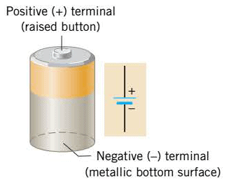 Within a battery, a chemical reaction occurs that transfers electrons from one terminal (leaving it positively charged) to another terminal (leaving it negatively charged). The drawing illustrates the symbol used to represent a battery in circuit drawings.
When a 1.5-V battery is connected with a headlight between its terminals. The positive terminal, point A, has a potential that is 1.5 V higher than the potential at the negative terminal, point B; in other words, $V_A - V_B = 1.5$ V. Positive charges would be repelled from the positive terminal and would travel through the wires and headlight toward the negative terminal. As the charges pass through the headlight, virtually all their potential energy is converted into heat, which causes the filament to glow "white hot" and emit light. When the charges reach the negative terminal, they no longer have any potential energy. The battery then gives the charges an additional "shot" of potential energy by moving them to the higher-potential positive terminal, and the cycle is repeated. In raising the potential energy of the charges, the battery does work on them and draws from its reserve of chemical energy to do so.
Electromotive Force: Terminal Voltage
Because of the positive and negative charges on the battery terminals, an electric potential difference exists between them. The maximum potential difference is called the electromotive force(emf) of the battery (The word "force" appears in this context for historical reasons, even though it is incorrect. As we have seen, electric potential is energy per unit charge, which is not force), for which the symbol $\varepsilon$ is used.
In a typical car battery, the chemical reaction maintains the potential of the positive terminal at a maximum of 12 volts (12 joules/coulomb) higher than the potential of the negative terminal, so the emf is $\varepsilon$ = 12 V. Thus, one coulomb of charge emerging from the battery and entering a circuit has at most 12 joules of energy.
Interactive Demonstration: Current
|
|---|
Electric Power (Rate of Energy Transfer)
One of the most important functions of current in an electric circuit is to transfer energy from a source (a battery or a generator) to an electrical device (MP3 player, cell phone, etc.)
Power, which is defined in watts, W, measures the rate at which energy is transferred. If a battery transfers 1 J of chemical energy to electric energy each second, it is transferring energy at the rate of 1 J/s, or 1 W. The energy carried by an electric current depends on the charge transferred, $q$, and the potential difference across which it moves, $V$. Thus, $E =qV$. Since current, $I = q/t$, $q=It$, and the power, $P =E/t$, then the power of an electric device can be determined by multiplying voltage and current:
$$P=IV$$
When the charge moves through an electrical device, the charge loses electric potential energy. The principle of conservation of energy tells us that the decrease in potential energy must be accompanied by a transfer of energy to some other form (or forms). In a cell phone, for example, the energy transferred appears as light energy (coming from the display screen), sound energy (emanating from the speaker), thermal energy (due to heating of the internal circuitry), and so on.
The charge in a circuit can also gain electrical energy. For example, when it moves through the battery, the charge goes from a lower to a higher potential, just the opposite of what happens in the electrical device. In this case, the charge gains electric potential energy. Consistent with the conservation of energy, this increase in potential energy must come from somewhere; in this case it comes from the chemical energy stored in the battery. Thus, the charge regains the energy it lost to the device, at the expense of the chemical energy of the battery.
Monthly electric bills specify the cost for the energy consumed during the month. Energy is the product of power and time, and electric companies compute your energy consumption by expressing power in kilowatts and time in hours. Therefore, a commonly used unit for energy is the kilowatt.hour (kWh)[1 kWh= $3.60 \times 10^6$ J of energy]. For instance, if you used an average power of 1440 watts (1.44 kW) for 30 days (720 h), your energy consumption would be ( 1.44 kW) (720 h) = 1040 kWh. At a cost of $\$$0.12 per kWh, your monthly bill would be $\$$125.
Interactive Demonstration: Electric Power
|
|---|
Resistance and Resistivity
Suppose two conductors have a potential difference between them. If they are connected with a copper rod, a large current is created. On the other hand, putting a glass rod between them creates almost no current. The property determining how much current will flow is called resistance.
Here is some of the factors that impact resistance:
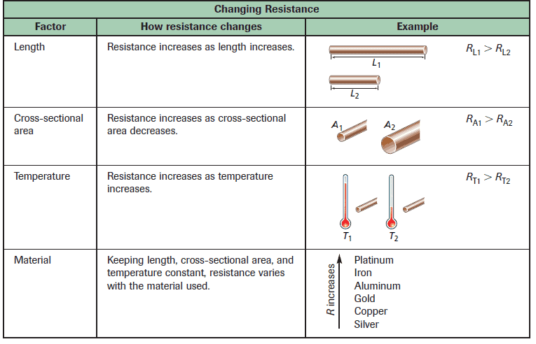
For a wide range of materials, the resistance of a piece of material of length $L$ and cross-sectional area $A$ is:
$$ R= \rho \dfrac{L}{A} $$
where $\rho$ is a proportionality constant known as the resistivity of the material. The unit for resistivity is the ohm.meter ($\Omega$.m) and the following Table lists resistivities values for various materials:
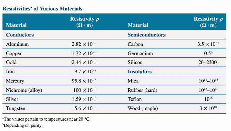
All the conductors in the table are metals and have small resistivities. Insulators such as rubber have large resistivities. Materials like germanium and silicon have intermediate resistivity values and are, accordingly, called semiconductors.
Resistivity is an inherent property of a material, inherent in the same sense that density is an inherent property. Resistance, on the other hand, depends on both the resistivity and the geometry of the material.
The resistivity of a material depends on temperature. In metals, the resistivity increases with increasing temperature, whereas in semiconductors the reverse is true. For many materials and limited temperature ranges, it is possible to express the temperature dependence of the resistivity as follows:
$$ \rho = \rho_0 [1+ \alpha (T - T_0)] $$
In this expression $\rho$ and $\rho_0$ are the resistivities at temperatures $T$ and $T_0$ , respectively. The term $\alpha$ has the unit of reciprocal temperature and is the temperature coefficient of resistivity. When the resistivity increases with increasing temperature, $\alpha$ is positive, as it is for metals. When the resistivity decreases with increasing temperature, $\alpha$ is negative, as it is for the semiconductors carbon, germanium, and silicon. Both sides of this Equation can be multiplied by $L/A$ to show that resistance depends on temperature according to: $ R = R [1+ \alpha (T - T_0)] $
There is an important class of materials whose resistivity suddenly goes to zero below a certain temperature $T_c$, which is called the critical temperature and is commonly a few degrees above absolute zero. Below this temperature, such materials are called superconductors. The name derives from the fact that with zero resistivity, these materials offer no resistance to electric current and are, therefore, perfect conductors. Once a current is established in a superconducting ring, the current continues indefinitely without the need for an emf. Currents have persisted in superconductors for many years without measurable decay. In contrast, the current in a nonsuperconducting material drops to zero almost immediately after the emf is removed.
Many metals become superconductors only at very low temperatures, such as aluminum ($T_c$ = 1.18 K), tin ($T_c$ = 3.72 K), lead ($T_c$ = 7.20 K), and niobium ($T_c$ = 9.25 K). Materials involving copper oxide complexes have been made that undergo the transition to the superconducting state at 175 K. Superconductors have many technological applications, including magnetic resonance imaging, magnetic levitation of trains, cheaper transmission of electric power, powerful (yet small) electric motors, and faster computer chips.
Ohm’s Law (Measuring Resistance in Simple Circuits)
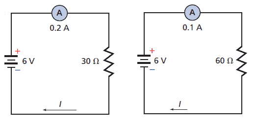
In the simplest case, the current $I$ is directly proportional to the voltage $V$; that is, $I \propto V$. Thus, a voltage of 12 V leads to twice as much current as a voltage of 6 V, when each is connected to the same circuit.
Resistance is measured by placing a potential difference across a conductor and dividing the voltage by the current. The resistance, $R$, is defined as the ratio of electric potential difference, $V$, to the current, $I$.
$$ \dfrac{V}{I}=R= \text{constant} $$
For many materials (e.g., metals), the ratio $V/I$ is the same for a given piece of material over a wide range of voltages and currents. In such a case, the resistance is a constant. Then, the relation $R = V/I$ is referred to as Ohm's law, after the German physicist Georg Simon Ohm (1789- 1854), who discovered it.
A device having constant resistance independent of the potential difference obeys Ohm’s law. Many important devices, however, do not. A radio and a pocket calculator contain many devices, such as transistors and diodes, that do not obey Ohm’s law. Even a lightbulb has resistance that depends on its temperature and does not obey Ohm’s law.
The SI unit for resistance is a volt per ampere, which is called an ohm and is represented by the Greek capital letter omega ($\Omega$). One ohm ($1 \Omega$) is the resistance permitting an electric charge of 1 A to flow when a potential difference of 1 V is applied across the resistance. Ohm's law is not a fundamental law of nature like Newton's laws of motion. It is only a statement of the way certain materials behave in electric circuits.
The resistance can have a wide range of values. Wires used to connect electric devices have low resistance. Because wires have so little resistance, there is almost no potential drop across them. To produce greater potential drops, a large resistance concentrated into a small volume is necessary. A resistor is a device designed to have a specific resistance. Resistors may be made of graphite, semiconductors, or wires that are long and thin. Such resistors play an important role in electric circuits, where they are typically used to limit the amount of current and establish the desired voltage levels.
 Resistors often are used to control the current in circuits or parts of circuits, see the Figure. Sometimes, a smooth, continuous variation of the current is desired. For example, the speed control on some electric motors allows continuous, rather than step-by-step, changes in the rotation of the motor. To achieve this kind of control, a variable resistor, called a potentiometer, is used. Examples of using variable resistors to adjust the levels of electrical energy can be found on the front of a TV: the volume, brightness, contrast, tone, and hue controls are all variable resistors.
In drawing electric circujts we follow the usual conventions: ( 1) a zigzag line (-/\/\/\-) represents a resistor and (2) a straight line (----) represents an jdeal conducting wire, or one with a negligible resistance.
Diagramming Circuits
A simple circuit can be described in words. It can also be depicted by photographs or artists’ drawings of the parts. Most frequently, however, an electric circuit is drawn using standard symbols for the circuit elements. Such a diagram is called a circuit schematic. Some of the symbols used in circuit schematics are shown in the following table:
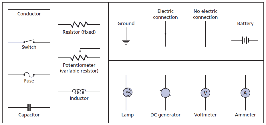
An ammeter measures current and a voltmeter measures potential differences. Each instrument has two terminals, usually labeled + and -. A voltmeter measures the potential difference across any component of a circuit. When connecting the voltmeter in a circuit, always connect the + terminal to the end of the circuit component that is closer to the positive terminal of the battery, and connect the - terminal to the other side of the component.
Digital lab: How Can You Change Current In An Electric Circuit?
|
Animated Physics: Ohm’s Law
|
Interactive Demonstration: Resistance
|
|---|---|---|
Digital Investigation: Circuits and Ohm's Law
|
Digital simulation: Flashlight Circuit
|
Digital Figure: Flashlight
|
Alternating Current versus Direct Current
Many electric circuits use batteries and involve direct current (dc). However, there are considerably more circuits that operate with alternating current (ac), in which the charge flow reverses direction periodically. The common generators that create ac electricity depend on magnetic forces for their operation. In an ac circuit, these generators serve the same purpose as a battery serves in a dc circuit; that is, they give energy to the moving electric charges. This section deals with ac circuits that contain only resistance.
Since the electrical outlets in a house provide alternating current, we all use ac circuits routinely. For example, the heating element of a toaster is essentially a thin wire of resistance R and becomes red hot when electrical energy is dissipated in it. The following Figure shows the ac circuit that is formed when a toaster is plugged into a wall socket.
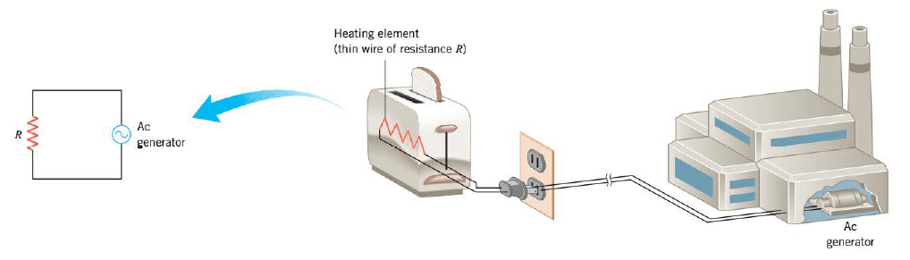
The circuit schematic in the picture introduces the symbol (~) that is used to represent the generator. In this case, the generator is located at the electric power company.
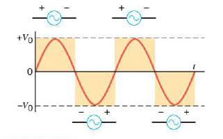 This Figure shows a graph that records the voltage V produced between the terminals of the ac generator in the above circuit at each moment of time $t$. This is the most common type of ac voltage. It fluctuates sinusoidally between positive and negative values:
$$ V=V_0 \sin 2 \pi f t$$
where $V_0$ is the maximum or peak value of the voltage, and $f$ is the frequency (in cycles/s or Hz) at which the voltage oscillates. The angle $2 \pi ft$ in this Equation is expressed in radians, so a calculator must be set to its radian mode before the sine of this angle is evaluated. In the United States, the voltage at most home wall outlets has a peak value of approximately $V_0$ = 170 volts and oscillates with a frequency of $f$= 60 Hz. Thus, the period of each cycle is $\frac{1}{60}$ s, and the polarity of the generator terminals reverses twice during each cycle, as this Figure indicates.
The current in an ac circuit also oscillates. In circuits that contain only resistance, the current reverses direction each time the polarity of the generator terminals reverses. Thus, the current in a circuit like that in the above drawing would have a frequency of 60 Hz and would change direction twice during each cycle. Substituting $ V=V_0 \sin 2 \pi f t$ into $V = IR$ shows that the current can be represented as:
$$ I=\dfrac{V_0}{R} \sin 2 \pi f t = I_0 \sin 2 \pi f t$$
The peak current is given by $I_0= \dfrac{V_0}{R}$, so it can be determined if the peak voltage and the resistance are known.
 The power delivered to an ac circuit by the generator is given by $P = IV$, just as it is in a dc circuit. However, since both $I$ and $V$ depend on time, the power fluctuates as time passes. Substituting $V$ and $I$ into $P = IV$ gives:
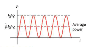
$$ P= I_0 V_0 \sin^2 2 \pi f t$$
This expression is plotted in the Figure.
Since the power fluctuates in an ac circuit, it is customary to consider the average power $\bar{P}$, which is one-half the peak power, as the Figure indicates:
$$\bar{P} = \frac{1}{2} I_0 V_0$$
On the basis of this expression, a kind of average current and average voltage can be introduced that are very useful when discussing ac circuits. A rearrangement of the above Equation reveals that:
$$\bar{P} = \left( \frac{I_0}{\sqrt{2}} \right) \left( \frac{V_0}{\sqrt{2}} \right) = I_{rms} V_{rms}$$
$I_{rms}$ and $V_{rms}$ are called the root-mean-square (rms) current and voltage, respectively, and may be calculated from the peak values by dividing them by $\sqrt{2}$ (This applies only for sinusoidal current and voltage):
$$I_{rms}= \frac{I_0}{\sqrt{2}}$$ $$V_{rms}= \frac{V_0}{\sqrt{2}}$$
Since the normal maximum ac voltage at a home wall socket in the United States is $V_0$ = 170 volts, the corresponding rms voltage is $V_{rms}$ = (170 volts)/ $\sqrt{2}$ = 120 volts. Instructions for electrical devices usually specify this rms value. Similarly, when we specify an ac voltage or current it is an rms value, unless indicated otherwise. When we specify ac power, it is an average power, unless stated otherwise.
Except for dealing with average quantities, the relation $\bar{P} = I_{rms} V_{rms}$ has the same form as Equation ($P = IV$). Moreover, Ohm's law can be written conveniently in terms of rms quantities:
$$V_{rms} = I_{rms} R$$
Substituting this Equation into $\bar{P}$ Equation shows that the average power can be expressed in the following ways:
$$\bar{P} = I_{rms} V_{rms} = I_{rms}^2 R = \dfrac{V_{rms}^2}{R} $$
These expressions are completely analogous to $P =I V = I^2 R = \dfrac{V^2}{R}$ Equations for dc circuits.

You don`t have permission to comment here!
Report