Electromagnetic Induction and AC Circuits
Electromagnetic induction
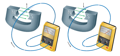
There are a number of ways a magnetic field can be used to generate an electric current:
(a) When there is no relative motion between the coil of wire and the bar magnet, there is no current in the coil.
(b) A current is created in the coil when the magnet moves toward the coil.
(c) A current also exists when the magnet moves away from the coil, but the direction of the current is opposite to that in (b).
The current in the coil is called an induced current because it is brought about ( or "induced") by a changing magnetic field. Since a source of emf (electromotive force) is always needed to produce a current, the coil itself behaves as if it were a source of emf. This emf is known as an induced emf. Thus, a changing magnetic field induces an emf in the coil, and the emf leads to an induced current.
In each of the previous examples, both an emf and a current are induced in the coil because the coil is part of a complete, or closed, circuit. If the circuit were open-perhaps because of an open switch-there would be no induced current. However, an emf would still be induced in the coil, whether the current exists or not. The phenomenon of producing an induced emf with the aid of a magnetic field is called electromagnetic induction. The next section discusses yet another method by which an induced emf can be created.
Digital simulation: Electromagnetic Induction
|
Digital figure: magnet and coil
|
Digital figure: automobile
|
|---|
Motional Emf
When a conducting rod moves through a constant magnetic field, an emf is induced in the rod. This special case of electromagnetic induction arises as a result of the magnetic force that acts on a moving charge we saw before. Consider the metal rod of length $L$ moving to the right. The velocity $\vec{v}$ of the rod is constant and is perpendicular to a unifo1m magnetic field $\vec{B}$ . Each charge $q$ within the rod also moves with a velocity $\vec{v}$ and experiences a magnetic force of magnitude $F = qvB$. By using RHR-1, it can be seen that the mobile, free electrons are driven to the bottom of the rod, leaving behind an equal amount of positive charge at the top. (Remember to reverse the direction of the force that RHR-1 predicts, since the electrons have a negative charge). The positive and negative charges accumulate until the attractive electric force that they exert on each other becomes equal in magnitude to the magnetic force. When the two forces balance, equilibrium is reached and no further charge separation occurs.
The separated charges on the ends of the moving conductor give rise to an induced emf, called a motional entf because it originates from the motion of charges through a magnetic field. The emf exists as long as the rod moves. If the rod is brought to a halt, the magnetic force vanishes, with the result that the attractive electric force reunites the positive and negative charges and the emf disappears. The emf of the moving rod is analogous to the emf between the terminals of a battery. However, the emf of a battery is produced by chemical reactions, whereas the motional emf is created by the agent that moves the rod through the magnetic field.
The fact that the electric and magnetic forces balance at equilibrium can be used to determine the magnitude of the motional emf $\varepsilon$:
$$\varepsilon = BLv$$
Magnetic Flux
Motional emf, as well as any other type of induced emf, can be described in terms of a concept called magnetic flux. Magnetic flux is analogous to electric flux, which deals with the electric field and the surface through which it passes. Magnetic flux is defined in a similar way by bringing together the magnetic field and the surface through which it passes.
The general expression for magnetic flux is:
$$ \Phi = (B \cos \theta) A = BA \cos \theta$$
Faraday’s Law of Induction and Lenz’s Law
Faraday discovered that whenever there is a change in flux through a loop of wire, an emf is induced in the loop. In this context, the word "change" refers to a change as time passes. A flux that is constant in time creates no emf. Faraday's law of electromagnetic induction is expressed by bringing together the idea of magnetic flux and the time interval during which it changes. In fact, Faraday found that the magnitude of the induced emf is equal to the time rate of change of the magnetic flux.
Often the magnetic flux passes through a coil of wire containing more than one loop (or turn). If the coil consists of $N$ loops, and if the same flux passes through each loop, it is found experimentally that the total induced emf is $N$ times that induced in a single loop. An analogous situation occurs in a flashlight when two 1.5-V batteries are stacked in series on top of one another to give a total emf of 3.0 volts. For the general case of N loops, the total induced emf is described by Faraday's law of electromagnetic induction in the following manner:
$$\varepsilon = -N \dfrac{\Delta \Phi}{\Delta t}$$
Faraday's law states that an emf is generated if the magnetic flux changes for any reason. Since the flux is given by Equation $\Phi = BA \cos \theta$, it depends on the three factors, $B$, $A$, and $\theta$, any of which may change.
Lenz's Law
An induced emf drives current around a circuit just as the emf of a battery does. With a battery, conventional current is directed out of the positive terminal, through the attached device, and into the negative terminal. The same is true for an induced emf, although the locations of the positive and negative terminals are generally not as obvious. Therefore, a method is needed for determining the polarity or algebraic sign of the induced emf, so the terminals can be identified. As we discuss this method, it will be helpful to keep in mind that the net magnetic field penetrating a coil of wire results from two contributions. One is the original magnetic field that produces the changing flux that leads to the induced emf. The other arises because of the induced current, which, like any current, creates its own magnetic field. The field created by the induced current is called the induced magnetic field.
To determine the polarity of the induced emf, we will use a method based on a discovery made by the Russian physicist Heinrich Lenz (1804-1865). This discovery is known as Lenz's law:
The induced emf resulting from a changing magnetic flux has a polarity that leads to an induced current whose direction is such that the induced magnetic field opposes the original flux change.
Animated Physics: Ways of Inducing Current
|
Interactive Demonstration: Induced EMF and Current
|
|---|
The Electric Generators
Electric generators, produce virtually all of the world's electrical energy. A generator produces electrical energy from mechanical work, which is just the opposite of what a motor does. In a motor, an input electric current causes a coil to rotate, thereby doing mechanical work on any object attached to the shaft of the motor. In a generator, the shaft is rotated by some mechanical means, such as an engine or a turbine, and an emf is induced in a coil. If the generator is connected to an external circuit, an electric current is the output of the generator.
The Countertorque in a Generator
Some power-generating stations burn fossil fuel (coal, gas, or oil) to heat water and produce pressurized steam for turning the blades of a turbine whose shaft is linked to the generator. Others use nuclear fuel or falling water as a source of energy. As the turbine rotates, the generator coil also rotates and mechanical work is transformed into electrical energy.
The devices to which the generator supplies electricity are known collectively as the "load," because they place a burden or load on the generator by taking electrical energy from it. If all the devices are switched off, the generator runs under a no-load condition, because there is no current in the external circuit and the generator does not supply electrical energy. Then, work needs to be done on the turbine only to overcome friction and other n1echanical losses within the generator itself, and fuel consumption is at a minimum.
Take a situation in which a load is connected to a generator. Because there is now a current in the coil of the generator and the coil is situated in a magnetic field, the current experiences a magnetic force $\vec{F}$. A magnetic force acting on the left side of the coil, with the direction of $\vec{F}$ given by RHR-1 . A force of equal magnitude but opposite direction also acts on the right side of the coil. The magnetic force $\vec{F}$ gives rise to a countertorque that opposes the rotational motion. The greater the current drawn from the generator, the greater the countertorque, and the harder it is for the turbine to turn the coil. To compensate for this countertorque and keep the coil rotating at a constant angular speed, work must be done by the turbine, which means that more fuel must be burned.
This is another example of the law of conservation of energy, since the electrical energy consumed by the load must ultimately come from the energy source used to drive the turbine.
Eddy Currents and Magnetic Damping
Induced currents are not always confined to well-defined paths such as in wires.
Consider, for example, a rotating metal wheel. An external magnetic field is applied to a limited area of the wheel and points into the page. The section of wheel in the magnetic field has an emf induced in it because the conductor is moving, carrying electrons with it. The flow of induced (conventional) current in the wheel is upward in the region of the magnetic field, and the current follows a downward return path outside that region. Why? According to Lenz’s law, the induced currents oppose the change that causes them.
Consider the left side of the section with magnetic field, where the magnetic field is zero but is just about to enter a region where points into the page.To oppose this inward increase in magnetic field, the induced current is counterclockwise to produce a field pointing out of the page (RHR1). Similarly, the right side is about to move to a point where the magnetic field is zero; hence the current is clockwise to produce an inward field opposed to this decreasing flux inward. These currents are referred to as eddy currents. They can be present in any conductor that is moving across a magnetic field or through which the magnetic flux is changing.
In the above example, the magnetic field exerts a force on the induced currents it has created, and that force opposes the rotational motion. Eddy currents can be used in this way as a smooth braking device on, say, a rapid-transit car. In order to stop the car, an electromagnet can be turned on that applies its field either to the wheels or to the moving steel rail below. Eddy currents can also be used to dampen (reduce) the oscillation of a vibrating system, which is referred to as magnetic damping
Eddy currents, however, can be a problem. For example, eddy currents induced in the armature of a motor or generator produce heat ($P = I \varepsilon$) and waste energy.
To reduce the eddy currents, the armatures are laminated; that is, they are made of very thin sheets of iron that are well insulated from one another. The total path length of the eddy currents is confined to each slab, which increases the total resistance; hence the current is less and there is less wasted energy
Back Emf Generated by an Electric Motor
A generator converts mechanical work into electrical energy; in contrast, an electric motor converts electrical energy into mechanical work. Both devices are similar and consist of a coil of wire that rotates in a magnetic field. In fact, as the armature of a motor rotates, the magnetic flux passing through the coil changes and an emf is induced in the coil. Thus, when a motor is operating, two sources of emf are present:
(1) the applied emf $V$ that provides current to drive the motor (e.g., from a 120-V outlet)
(2) the emf $\varepsilon$ induced by the generator-like action of the rotating coil.
Consistent with Lenz's law, the induced emf $\varepsilon$ acts to oppose the applied emf $V$ and is called the back emf or the counter emf of the motor. The greater the speed of the motor, the greater is the flux change through the coil, and the greater is the back emf. Because $V$ and $\varepsilon$ have opposite polarities, the net emf in the circuit is $V - \varepsilon$. $R$ is the resistance of the wire in the coil, and the current $I$ drawn by the motor is determined from Ohm's law as the net emf divided by the resistance:
$$I=\dfrac{V-\varepsilon}{R}$$
And we see that when a motor is just starting, there is little back emf, and, consequently, a relatively large current exists in the coil. As the motor speeds up, the back emf increases until it reaches a maximum value when the motor is rotating at normal speed. The back emf becomes almost equal to the applied emf, and the current is reduced to a relatively small value, which is sufficient to provide the torque on the coil needed to overcome frictional and other losses in the motor and to drive the load (e.g., a fan).
Interactive Demonstration: rms Current and emf
|
Digital Interactives: Electromagnetic Induction
|
|---|
Mutual Inductance and Self-Inductance
Mutual Inductance
We have seen that an emf can be induced in a coil by keeping the coil stationary and moving a magnet nearby, or by moving the coil near a stationary magnet. Another important method of inducing an emf. Here, two coils of wire, the primary coil and the secondary coil, are placed close to each other. The primary coil is the one connected to an ac generator, which sends an alternating current $I_P$ through it. The secondary coil is not attached to a generator, although a voltmeter is connected across it to register any induced emf.
The current-carrying primary coil is an electromagnet and creates a magnetic field in the surrounding region. If the two coils are close to each other, a significant fraction of this magnetic field penetrates the secondary coil and produces a magnetic flux. The flux is changing, since the current in the primary coil and its associated magnetic field are changing. Because of the change in flux, an emf is induced in the secondary coil.
The effect in which a changing current in one circuit induces an emf in another circuit is called mutual induction.
Self-Inductance
In all the examples of induced emfs presented so far, the magnetic field has been produced by an external source, such as a permanent magnet or an electromagnet. However, the magnetic field need not arise from an external source. An emf can be induced in a current-carrying coil by a change in the magnetic field that the current itself produces. For instance, take a coil connected to an ac generator. The alternating current creates an alternating magnetic field that, in tum, creates a changing flux through the coil. The change in flux induces an emf in the coil, in accord with Faraday's law. The effect in which a changing current in a circuit induces an emf in the same circuit is referred to as self-induction.
Transformers
One of the most important applications of mutual induction and self-induction takes place in a transformer. A transformer is a device that is used to increase or decrease an ac voltage. For instance, whenever a cordless device (e.g., a cell phone) is plugged into a wall receptacle to recharge the batteries, a transformer plays a role in reducing the 120-V ac voltage to a much smaller value. Typically, between 3 and 9 V are needed to energize batteries. In another example, a picture tube in a television set needs about 15000 V to accelerate the electron beam, and a transformer is used to obtain this high voltage from the 120 V at a wall socket.
Animated Physics: Transformers
|
Concept Map: Induced Current
|
Interactive Demonstration: Transformers
|
|---|---|---|
Digital figure: transmission of electric power
|
Capacitors and Capacitive Reactance
Our experience with capacitors so far has been in dc circuits, charge flows in a dc circuit only for the brief period after the battery voltage is applied across the capacitor. In other words, charge flows only while the capacitor is charging up. After the capacitor becomes fully charged, no more charge leaves the battery. However, suppose that the battery connections to the fully charged capacitor were suddenly reversed. Then charge would flow again, but in the reverse direction, until the battery recharges the capacitor according to the new connections. In an ac circuit what happens is similar. The polarity of the voltage applied to the capacitor continually switches back and forth, and, in response, charges flow first one way around the circuit and then the other way. This flow of charge, surging back and forth, constitutes an alternating current. Thus, charge flows continuously in an ac circuit containing a capacitor.
Digital figure: circuit containing only a capacitor
|
|---|
Inductors and Inductive Reactance
As we discusses, an inductor is usually a coil of wire, and the basis of its operation is Faraday's law of electromagnetic induction. According to Faraday's law, an inductor develops a voltage that opposes a change in the current. This voltage $V$ is given by $V = -L( \Delta I / \Delta t)$, where $\Delta I / \Delta t$ is the rate at which the current changes and $L$ is the inductance of the inductor. In an ac circuit the current is always changing, and Faraday's law can be used to show that the rms voltage across an inductor is:
$$V_{rms} = I_{rms} X_L$$
Digital figure: circuit containing only a inductor
|
|---|
Circuits Containing Resistance, Capacitance, and Inductance
Capacitors and inductors can be combined along with resistors in a single circuit. The simplest combination contains a resistor, a capacitor, and an inductor in series. In a series RCL circuit the total opposition to the flow of charge is called the impedance of the circuit and comes partially from (1) the resistance $R$, (2) the capacitive reactance $X_c$, and (3) the inductive reactance $X_L$. It is tempting to follow the analogy of a series combination of resistors and calculate the impedance by simply adding together $R$, $X_c$, and $X_L$. However, such a procedure is not correct.
Digital simulation: AC Current with Only One Circuit Element
|
Digital simulation: RLC Circuit
|
|---|
Resonance in Electric Circuits
The behavior of the current and voltage in a series RCL circuit can give rise to a condition of resonance. Resonance occurs when the frequency of a vibrating force exactly matches a natural (resonant) frequency of the object to which the force is applied. When resonance occurs, the force can transmit a large amount of energy to the object, leading to a large-amplitude vibratory motion. We have already encountered several instances of resonance. For example, resonance can occur when a vibrating force acts on an object of mass $ m$ that is attached to a spring whose spring constant is $k$. In this case there is one natural frequency $f_0$, whose value is $f_0 = [l/(2 \pi)] \sqrt{k/m}$. Resonance also occurs when standing waves are set up on a string or in a tube of air. The string and tube of air have many natural frequencies, one for each allowed standing wave. As we will now see, a condition of resonance can also be established in a series RCL circuit. In this case there is only one natural frequency, and the vibrating force is provided by the oscillating electric field that is related to the voltage of the generator.
Semiconductor Devices
Semiconductor devices such as diodes and transistors are widely used in modern electronics. For example, an audio system in which small ac voltages ( originating in a compact disc player, an FM tuner, or a cassette deck) are amplified so they can drive the speaker(s). The electric circuits that accomplish the amplification do so with the aid of a de voltage provided by the power supply. In portable units the power supply is simply a battery. In nonportable units, however, the power supply is a separate electric circuit containing diodes, along with other elements. As we will see, the diodes convert the 60-Hz ac voltage present at a wall outlet into the dc voltage needed by the amplifier, which, in turn, performs its job of amplification with the aid of transistors.
Digital lesson: Electronic Technology
|
Digital figure: pnp transistor
|
|---|

You don`t have permission to comment here!
Report